Plinth
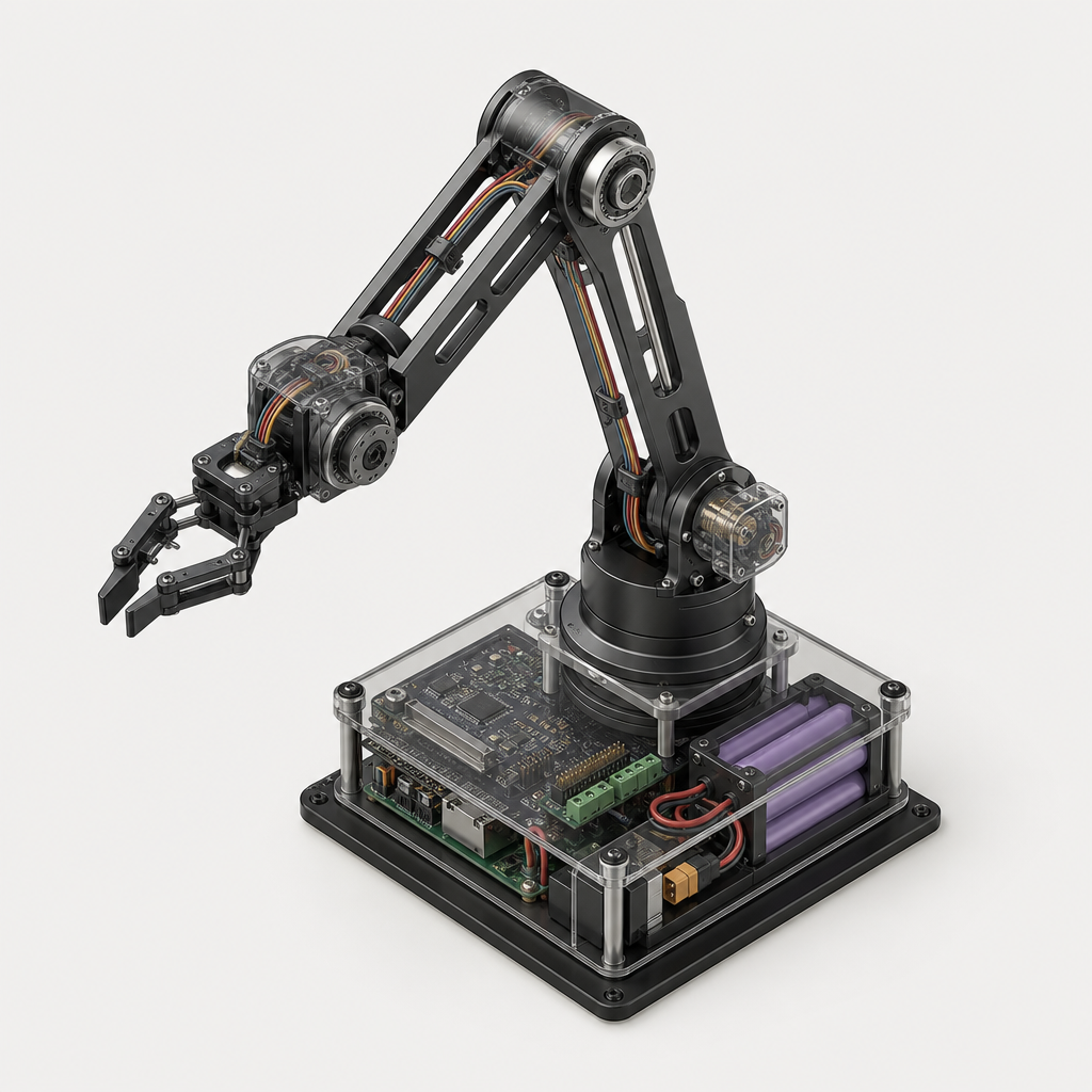
A 3-DOF robotic arm with inverse-kinematics demo firmware.
A 3-DOF robotic arm with inverse-kinematics demo firmware.
◢Bill of Materials
Actuation
Three servo motors providing rotational DOF at base, shoulder, and elbow joints of the robotic arm.
Structure
Mechanical arm links, base plate, hardware, and servo horns forming the physical 3-DOF arm structure.
3-DOF Robotic Arm Acrylic/Aluminum Link Kit (base, shoulder, elbow, end-effector brackets, servo horns, hardware)
other
ROBOT-ARM-3DOF-KIT
M3 Hex Bolt & Nut Assortment (100 pcs, arm assembly hardware)
other
M3-BOLT-NUT-100PK
Sensing
Feedback and user-input interface — potentiometers or joystick for manual end-effector target input during IK demo.
Compute
Main microcontroller running inverse kinematics firmware, servo control loops, and serial/USB communication for demo interface.
Power
Portable power supply and regulation providing clean 5V to servos and 3.3V/5V to the microcontroller from a battery source.
1000µF 16V Electrolytic Capacitor (bulk filter, power rail)
digikey
860020375017
4×AA Battery Holder with Leads (~6V supply)
digikey
BAT-HOLDER-4XAA
L7805CV 5V 1.5A Linear Voltage Regulator (TO-220)
digikey
L7805CV
Toggle Power Switch SPST (battery on/off, panel mount)
other
SPST-TOGGLE-PANEL
Total: $131.68 USD
◢CAD starter
◢Build Schedule
12-week plan
All parts ordered (incl. long-lead), dev environment fully configured
Order every component immediately — the 3-DOF Acrylic/Aluminum Link Kit, M3 Hex Bolt & Nut Assortment, and Toggle Power Switch SPST are long-lead unknowns and must be in-cart before anything else. In parallel, install the Arduino IDE, add the Arduino Nano Every board package, install the Adafruit PWM Servo Driver library, and smoke-test a blink sketch on the Nano Every to confirm the toolchain end-to-end.
You’ll need to know · 1
- Arduino IDE installation & board management - Arduino IDE 2 – Getting Started ↗
PCA9685 driving all three servos over I2C on the bench
Learn the PCA9685 I2C PWM driver: wire it to the Nano Every on a breadboard, step through the Adafruit library examples, and confirm each of the three SER0039 servos sweeps its full range under software control. Verifying servo travel now — before the arm kit arrives — de-risks mechanical assembly later.
You’ll need to know · 2
- I2C bus protocol basics (SDA/SCL, addressing) - SparkFun I2C Tutorial ↗
- Arduino analogWrite / PWM concepts - Arduino – Analog Output (PWM) ↗
Power circuit validated on breadboard; PCB layout ordered at fab
Build the portable power stage on a breadboard: 4×AA → toggle switch → L7805CV → 1000µF filter cap → 5V rail for servos and Nano Every. Measure rail voltage under servo stall load and confirm the regulator stays in spec. Simultaneously finalize the BusBoard SB830 PCB layout (Nano Every + regulator + headers) and place the fab order now — 2–3 week lead time puts boards back in hand by Week 5.
You’ll need to know · 2
- Linear voltage regulator wiring (LM78xx family) - SparkFun – Voltage & Regulation Basics ↗
- Decoupling / bulk capacitor placement - Adafruit – Guide to Excellent Soldering ↗
3-axis potentiometer input reading and mapped to servo angles in firmware
Wire three 10kΩ potentiometers to Nano Every analog inputs (A0–A2) representing X, Y, Z target coordinates for the IK demo. Write firmware to read all three ADC channels, apply smoothing (rolling average), and map raw counts to physical workspace coordinates. Doing this before IK math isolates the sensor layer cleanly, making later integration straightforward.
You’ll need to know · 2
- Arduino analogRead and ADC resolution - Arduino – Analog Input ↗
- Voltage divider / potentiometer wiring - SparkFun – Voltage Dividers ↗
IK solver implemented & unit-tested via Serial Monitor
Derive and implement closed-form geometric IK for the 3-DOF arm (law of cosines for shoulder/elbow, atan2 for base rotation). Test purely over Serial Monitor — feed XYZ targets and print computed joint angles — before any hardware is attached. This decoupled approach lets you validate math correctness against known solutions before the arm kit arrives.
You’ll need to know · 2
- Trigonometry & vector math (atan2, law of cosines)
- C++ structs and floating-point arithmetic on Arduino
PCB soldered, power-on tested, and Nano Every running from battery
PCB boards arrive this week. Solder the Nano Every, L7805CV regulator, 1000µF cap, toggle switch header, and PCA9685 pin headers onto the BusBoard SB830. Power up from the 4×AA pack and verify 5V rail stability under load. Completing the permanent electronics platform now means mechanical assembly next week bolts onto a known-good electronics stack.
You’ll need to know · 2
- Through-hole soldering technique - Adafruit – Guide to Excellent Soldering ↗
- Multimeter voltage & continuity testing - SparkFun – How to Use a Multimeter ↗
3-DOF arm fully assembled with servos mounted and manually articulated
Arm kit and hardware should be in hand by now. Assemble base plate, shoulder link, elbow link, and end-effector bracket using M3 bolts; mount each SER0039 servo and press-fit servo horns. Manually rotate each joint through its range of motion to check for binding, backlash, and cable routing clearance before any firmware is applied. Physical assembly quality directly determines IK accuracy, so take care with joint alignment.
You’ll need to know · 2
- M3 metric fastener assembly & torque feel
- Servo horn alignment and press-fit techniques - Adafruit – Servos & Servo Horns ↗
Servo calibration complete; all joints reach commanded angles ±2°
Connect the assembled arm to the finished PCB and calibrate each servo: measure physical joint angles with a protractor, tune PCA9685 PWM pulse-width min/max per servo channel, and account for mechanical zero-offset of each horn. Store calibration constants in firmware. Accurate calibration is a prerequisite for meaningful IK execution — errors here propagate directly into end-effector positioning.
You’ll need to know · 2
- PWM pulse-width to servo angle mapping - Adafruit PCA9685 Guide ↗
- Physical angle measurement with protractor/caliper
IK firmware integrated end-to-end; pot inputs move arm to target XYZ
Merge the IK solver (Week 5), potentiometer input layer (Week 4), and calibrated servo output (Week 8) into a single firmware. Twist the pots and observe the arm tracking the commanded XYZ target in real time. Log commanded vs. actual joint angles over Serial to quantify positioning error and identify any singularity or workspace-boundary edge cases that need handling.
You’ll need to know · 2
- Modular Arduino firmware architecture (header/source split)
- IK solver math verified (completed Week 5)
Dedicated debug week: all known IK, mechanical, and power issues resolved
This is the dedicated testing and debugging week. Systematically sweep the full workspace and log end-effector position error; fix singularity handling and joint-limit clamping in the IK solver. Check for power-rail sag under simultaneous servo movement and add firmware-side slew-rate limiting if needed to reduce inrush current. Document every bug found and fix applied — this week's rigor is the margin of safety for the final demo.
You’ll need to know · 2
- Oscilloscope or logic analyzer use for PWM signal inspection - SparkFun – How to Use an Oscilloscope ↗
- Firmware serial logging and structured debugging approach
Portable enclosure complete; arm operates fully self-contained from battery
Secure the PCB and battery holder to the arm's base plate or a small enclosure panel (3D-printed bracket or laser-cut acrylic). Route and strain-relief all wiring. Run the full system on battery with no bench supply or USB cable attached; confirm portability requirement is met and that runtime is acceptable for a demo session. Take measurements on battery life under typical use.
You’ll need to know · 2
- Strain-relief and wire management techniques - Adafruit – Soldering & Wiring Guide ↗
- Battery capacity / current-draw estimation
Demo-ready: full integration tested, documentation complete, demo rehearsed
Run three full end-to-end demo cycles from cold boot: power on, sweep pots across workspace, verify arm tracks smoothly, power off cleanly. Write final documentation — schematic, BOM, IK derivation write-up, calibration procedure, and a short demo script. Record a 60-second video of the arm in action as a backup demo artifact. The project is complete and portable for any venue.
You’ll need to know · 2
- Schematic capture (KiCad or Fritzing)
- Technical writing and BOM documentation
Generated by Plinth's AI agents. Verify before purchasing parts, following the schedule, or making safety-critical decisions.
Generated by Plinth - turn a project idea into a real buildable plan.